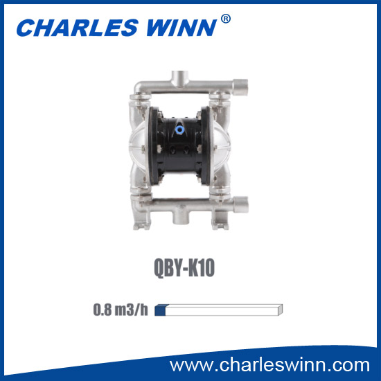
QBY-K10 Pneumatic Diaphragm Pump

Short Description
QBY-K is the third generation of pneumatic diaphragm pump developedby our company, and the first built-in type pneumatic diaphragm pumpinstalled with air valve as well. It adopts compressed air as power source,which ensures to completely suck various..
Back:DBY-80 DYNAMIC DIAPHRAGM PUMP
Next:QBY-K15 Pneumatic Diaphragm Pump
Tags:QBY-K10 Pneumatic Diaphragm PumpQuick Detail
QBY-K is the third generation of pneumatic diaphragm pump developed
by our company, and the first built-in type pneumatic diaphragm pump
installed with air valve as well. It adopts compressed air as power source,
which ensures to completely suck various corrosive liquids, granule-
containing liquids, as well as high viscosity volatile flammable virulent
liquids. Its quality has been widely recognized by clients for many years
since it was put into markets.
Working principle
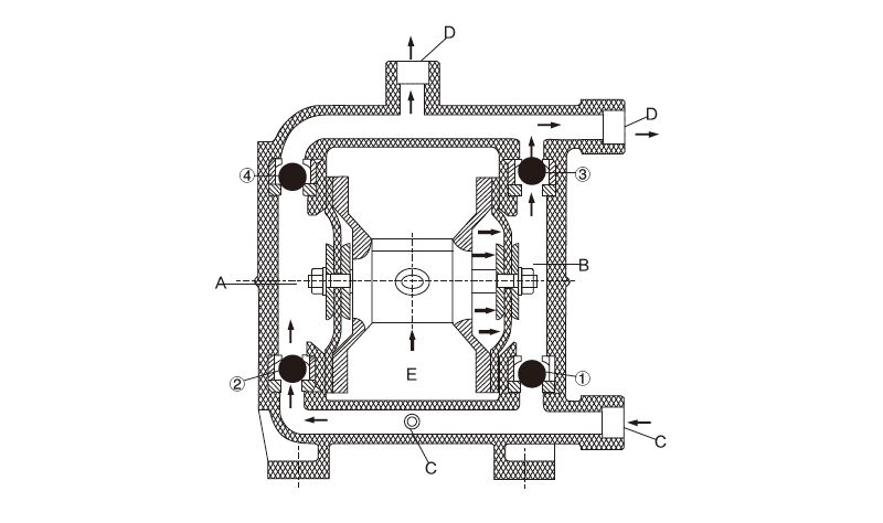
There installs each diaphragm in both aligned working cavities A & B, which can be connected together with a central coupling lever. The compression air enters the air distribution valve from the air entrance of the pump, draw the compression air into one cavity through the air distribution mechanism, push out the diaphragm movement in the cavity. The gas in another cavity will be drained. Once reaching the stroke terminal, the air distribution mechanism will automatically draw the compression air into another working cavity, push out the diaphragm to move towards the opposite direction, so as to let the both diaphragms continuously reciprocate motion in synchronism.
The compression air enters the air distribution valve from E shown as the diagram, let the diaphragm piece move towards the right direction. And the suction force in A chamber lets the medium flow into from C entrance, push out the ball valve ② to enter A chamber, the ball valve ④ will be locked due to the suction force; The medium in B chamber will be pressed, push out the ball valve ③ to flow out from the exit D. Meanwhile, let the ball valve ① close, prevent backflow. Such movement in circles will let the medium uninterruptedly suck from C entrance and drain from D exit.


