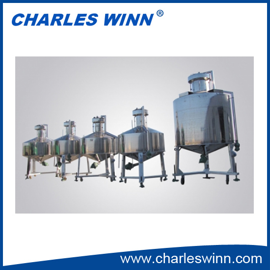
Product Name Standard Metal Gauge
Level 2
Uncertainty 0.025%
Material 304 SS 1Cr18Ni9Ti
Specifications 2000L, 3000L, 5000L
Use Test oil tank flowmeter
Implementation Rules JJG259-2005 "Standard Metal Measuring Instruments"
Product Description The product is a large-volume standard metal measuring device, suitable for oil depot, tank truck and underground tank inspection.
Second-class standard metal measuring instrument main technical indicators
1. The maximum allowable error is ±2.5×10⁻⁴
2. The indexing volume of the second-class standard metal measuring device shall not exceed 5×10⁻⁵ of its nominal capacity.
3. The main material of the second-class standard metal measuring device is made of 1Cr18Ni9Ti stainless steel plate.
4. The outer wall of the metal measuring device should be smooth and flat. The second metal measuring device should be touched by hand. Other metal measuring instruments should be observed with the naked eye, and there should be no unevenness. The inner wall should be polished to ensure the minimum liquid residue of the metal measuring device.
5. The lower part of the metal gauge foot should be equipped with adjustable bolts made of metal material and directly connected to the ground for adjustment level and static conduction.
6. The metal measuring device for detecting oil, in order to prevent foaming, a liquid pouring pipe is installed in the liquid inlet, the upper end of the pouring pipe should be slightly lower than the overflow cover of the metal measuring device, and the lower end should be located in the cylinder The lower part of the body part.
7. In order to ensure that there is no air bubbles when injecting the metal measuring device, the liquid residual amount on the wall of the liquid is the smallest when the liquid is discharged, and the angle between the upper cone and the lower cone should be ≤120°.
8. In order to ensure that the metal measuring device is in a horizontal state, an adjustable 0.05mm/m tubular level should be installed in the two mutually perpendicular horizontal directions of the main body of the metal measuring device (except for the metal measuring device during liquid level compensation)
9. In order to facilitate the adjustment of the liquid level, a fine adjustment liquid discharge valve can be installed at a position below the measuring neck of the metal measuring instrument.
10. The length of the measuring neck scale is determined according to the requirements of use; the liquid level scale of the nominal capacity should be located in the middle of the measuring neck.
11. A liquid level pipe should be installed at the metering neck reading position (the liquid level compensation type metal measuring device should be equipped with a liquid level pipe at 120° each other). The liquid level tube battalion is made of colorless transparent hard glass. The inner diameter of the tube is between DN8 and 16mm and should be uniform. The surface of the tube should be free from obstructing the observation of the liquid surface. The upper part of the tube should communicate with the overflow hood.
12. The metering neck ruler and the reading cursor are processed by the longitude chromium process (except for stainless steel materials). The zero point of the metering neck ruler should be at the bottom of the mounting position. The measuring neck scale and the reading and reading cursor markings should be clear, and the width of the marking line must not exceed 0.25 mm.
13. The plexiglass ring parallel to the liquid surface should be installed on the reading cursor. The ring should have an annular score line that is less than 0.25 mm wide and that the liquid level tube resides in the middle of the plexiglass ring. The connection of the plexiglass ring to the reading cursor is guaranteed to be relative.
14. The metal measuring device should be artificially aged to eliminate stress during manufacture to prevent it from being easily deformed due to stress changes during use.
15. The metal measuring device shall not have leakage after filling the medium or during the filling and discharging process; the connection between the valve and the metal measuring instrument body shall be firm and there shall be locking measures to prevent the volume of the metal measuring device due to the looseness of the valve. A change has occurred.
16. The exhaust capacity of the metal measuring device shall not exceed 0.2 dividing volume. The metal measuring device waits for 2 minutes in the trickle state, and there must be no intermittent continuous flow and surge discharge.
17, to ensure the mechanical properties of the metal measuring device, the maximum working pressure of the metal measuring device should be greater than 50KPa.
18. In accordance with the additional requirements of the vehicle metal measuring device, the tank body and the car body can be designed as a single structure.


